Where are they used?
Such connections are generally used to transmit only very small loads. Sometimes pins are used to secure parts together. There are also special shear elements of this type used as fuses. In addition to assemblies with shafts, such products are very often used to connect covers and housings.
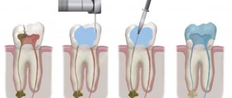
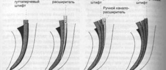
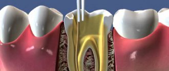
Another purpose of pin connections is prosthetics in dentistry. Using such elements, artificial teeth are attached.
What is a pin in a tooth for?
The decision on the advisability of pin extension is made by the doctor. Indications for using the pin method are:
- Destruction of the dental crown by more than 50 percent.
- Severe weakening of tooth enamel as a result of dental diseases or their treatment.
- The need to create a strong support for prosthetics.
- Extracting the tooth while the infection is being treated and then returning it to the socket.
Types of pins
When assembling various types of components, two main types of similar products are used:
- cylindrical;
- conical
Cylindrical pins, in turn, can be:
- spring split;
- perforated (with grooves).
Additional design elements of the pins may include threaded holes or protrusions. They are used for removing products from blind holes.
According to the functions performed in the assembly, three groups of pins are distinguished:
- installation;
- guides;
- fastening.
Does it hurt to put a pin in a tooth?
It doesn't hurt to put a pin in a tooth
, since with such prosthetics local anesthesia is used. Once the procedure is completed and the anesthesia wears off, there may be some discomfort, but there will be no pain even after the procedure.
Before making a final decision in favor of prosthetics using a pin, you need to consult with the dentistry department. The doctor must explain how the procedure will take place, why to insert this or that material, what the consequences are and whether there are guarantees for the installed structure. The pin is installed for a long time, so it is important to choose an experienced specialist who will select the right material and professionally carry out prosthetics.
Pin connection: GOST
In most cases, when assembling assemblies, standard pins are used, manufactured in compliance with GOST standards. They are different for each specific type of product. Thus, the production of simple-shaped pins is regulated by GOST 3128-70 (cylindrical) and GOST 3129-70 (conical). Such parts are usually made from steel grade 45. But GOST allows the use of material grades A12, 10 kp, 20 kp, etc. for this purpose. Expanded products are made from spring steel. Sometimes pins of different types are made from non-ferrous metals.
Of course, the nominal dimensions of these elements are also regulated by standards. GOST also provides for permissible deviations of the latter. This allows you to assign typical pin fits to the holes of bushings, shafts, covers and housings.
The designation of these products includes:
- the word "pin";
- product type;
- its dimensions;
- designation of the standard.
The type is indicated only if it is clearly defined by the standard. In the “dimensions” field, the diameter of the product and its length are indicated. Sometimes tolerance fields are also entered here.
Types of pins
Mechanical pins are made in various versions, depending on the type of connection and the need to disassemble it. What matters is the hardness of the material and the operating loads. Main types of pins:
- cylindrical;
- conical;
- spring;
- perforated
In total, approximately 16 types of fasteners are regularly used in industry and home workshops.
Cylindrical
Cylindrical products look like neatly cut and sanded pieces of wire. In fact, they are made from rolled steel and undergo a complex technological process of mechanical and heat treatment.
In addition to the size, which is determined by GOST 3128-70, cylindrical pins are not hardened, parts are divided into classes according to the design of the end:
- flat;
- with chamfers at 45⁰;
- rounded with a transition radius on one and both sides.
Download GOST 3128-70
Parts with flat ends are installed in through holes. They fit tightly into a material with high hardness. On the surface of low-carbon steels and non-ferrous metals, the corners of the ends leave burrs and scratches in the hole.
The smooth hard surface of holes in carbon hardened and alloy steels remains undamaged and the soft cylinder made of ST 45 is easily hammered and creates a strong connection.
For materials with medium hardness, a pin connection with chamfers on one or both sides is suitable. The cone formed at the end pushes apart and gradually crushes surface irregularities and easily fits into the hole.
Parts with a transition radius from the end to the cylindrical surface are the most difficult to manufacture. They are rarely used in mechanical engineering. They are most often used for fixing soft materials such as plastics and plastics.
Conical
Conical pins are placed on assemblies that will be frequently disassembled. The standard cone has a slope of 1:50. What are the types of non-standard parts that are separated into a separate section of special products? In mechanical engineering, especially when creating metallurgical equipment, it is possible to use 1:40 cones and other slopes.
When assembling parts for processing, if it is impossible to make a through hole, install conical pins with internal threads.
They are manufactured according to GOST 9464-79. The advantage of conical clamps is their tight fit throughout the entire period of operation. When the surface of the hole wears out, it only moves lower and centers itself.
The installation of conical pins allows them to be reused during dismantling and subsequent assembly of the unit. The latch does not change its shape and is placed in the same hole where it was.
To make holes for normalized conical pins, there is a number of drills in accordance with GOST 11177-84. Their angle of inclination corresponds exactly to the ratio of 1:50. To create a smoother surface, it is recommended to use reamers from the same group of tools.
Spring
The spring pin can be classified as a universal clamp. It is placed in the hole with interference. The more compressed, the better. The only limitation is that the ends of the longitudinal section should not rest against each other.
The cylindrical spring pin din 1481 is made from rolled sheets by rolling and hardening to fix the shape and impart elasticity. The group of din clamps has several varieties in design and a large list of standard sizes.
Advantages of using spring parts:
- holes are made with a wide range of sizes without reducing performance;
- possible repeated removal and installation back during assembly;
- firmly held in holes;
- easy to install.
DIN type spring products cannot work in units with heavy loads. They are thin-walled and wrinkle.
What is
Connections of this type are of the detachable type. When creating them, the parts of the assembly are first drilled. Moreover, it must be joint. That is, the parts are first stacked with each other in the same way as they will be located in the unit later during its operation. After this, the actual drilling takes place.
At the next stage, the pins themselves are inserted into the resulting holes. Cylindrical elements of this type are installed very tightly. That is, the pin always has a slightly larger diameter than the hole prepared for it.
In the event that the unit will be subjected to repeated assembly/disassembly during operation, conical pins rather than cylindrical pins are provided for it. This allows you to extend the service life of the structure. Since the cylindrical pins are inserted into the holes of the parts very tightly, after disassembly and assembly the assembly may lose its original performance qualities. That is, the connection may simply not be too strong.
The pins work during operation:
- for cutting (along the joint surface);
- to crumple.
It is based on these characteristics that calculations are made to determine their suitability for use in a particular unit. The working surfaces of both the pins and the parts being connected can be subject to collapse.
Advantages and disadvantages
In the manufacture of various types of assemblies, in addition to pin connections, wedge, key, and spline connections can be used. All of them are of the detachable type. Threaded connections of this type using screws, studs and bolts, profiles, and terminals are also very often used. Each of these types has both its advantages and disadvantages.
The advantages of pin connections include primarily:
- simplicity of design;
- ease of assembly/disassembly;
- precise centering of the parts to be connected.
Such connections have basically only one drawback. In any case, a hole drilled for the pin will weaken the part in the future. Terminal connections, for example, do not have such a disadvantage.
At the same time, the sockets for the pins must be processed very carefully. Otherwise, the product may subsequently bend. The need for precise processing of the hole increases the cost of manufacturing the assembly part.
Features of using cylindrical pins
The assembly of pin connections when fastening machine parts is usually performed using smooth products. In the same way, the usual fixation of structural elements of the machine during its operation is usually carried out. In this case, two smooth pins are most often used.
To fix the position of parts, perforated products of this type can also be used. Their main advantage, compared to smooth ones, is that they do not require reaming the holes. In the absence of additional fastenings, such elements are also more reliable in terms of falling out. As with the use of conical pins, when using drilled cylindrical pins, assembly/disassembly of the connection can be carried out repeatedly during operation.
In static connections, cylindrical products are installed with interference. In moving ones, they are mounted with the obligatory riveting of the ends. Spring cylindrical pins are usually mounted in lightly loaded connections. The tension when using them is created by reducing the diameter of the hole. Installation types of pins in fit connections are installed with an interference fit with one of the parts. On the other hand, they are mounted with a H7/h6 or H7/js6 fit.
Installation (cylindrical, conical, "lying") pins
0
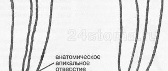
Alignment (control) pins are used in cases where it is necessary to accurately fix the position of one part relative to another (for example, the position of the cover of a detachable sliding bearing relative to its housing), as well as to perceive transverse forces acting in the plane of the separation of two parts (for example, to transmit torque moment in the flange connection of the shafts).
There are two types of locating pins: cylindrical and conical removable.
Cylindrical pins (Fig. 217) are usually installed tightly (in an interference fit) in one of the parts to be connected; the protruding end of the pin fits into the hole of another part according to the H7/js6 or H7/h6 fit.
The shape of the pin is of great importance for the correct operation and durability of the connection. The simplest form - cylindrical with lead-in chamfers at an angle of 45° (Fig. 217, I) - is the least satisfactory: the edges of the chamfers (when pressing the pin and when putting on the detachable part) damage the walls of the holes.
Sloping chamfers at an angle of 10-20° are somewhat better (Fig. 217, II). However, here too, although to a lesser extent, the same phenomenon is observed. It is better when the ends of the pins (at least the end included in the removable part) have fillets (Fig. 217, III).
The optimal design is shown in Fig. 217, IV. Here, the input end of the pin is made with a fillet of variable radius, smoothly turning into the cylindrical surface of the pin. This form is widely used for pins installed in parts made of light alloys. The manufacture of such pins is somewhat more complicated, but they provide convenient installation and long service life of the connection.
In all cases, lead-in chamfers on the holes of the parts to be joined are required. In the seat, chamfers are necessary to facilitate pressing of the pin; in products made of ductile metals, chamfers, in addition, prevent bulging of the material at the edges of the socket. In the holes of detachable parts, chamfers are needed to facilitate installation.
In products made of soft materials, for example, plastics, the hole under the input end of the pin is lined (Fig. 217, V). The fittings are attached to the product using threads, crimping, etc.
The locating pins are made of high-carbon steel; for critical power connections, they are made of alloy steel, hardened to a hardness of HRC 50-60. The working surfaces of the pins are processed no lower than 6th quality with a roughness parameter Ra = 0.32–0.63 µm.
A pin is usually installed in a blind hole using an interference fit. The smaller the diameter of the pin and the softer the material of the product, the greater the tension in the connection. In products made of light alloys, interference fits r6, s6, t7, u7 are used. Nevertheless, the pins, as a rule, provide additional protection against falling out if the tension is accidentally loosened (see Fig. 224).
Steel, high-strength and malleable cast iron, bronze - l = 2d Gray cast iron - l = (2-2.5)d Aluminum, magnesium, zinc alloys - l = (2.5-3)d Plastics (without lining) - l = (3.3—3.5)d
The pressing depth l (Fig. 218) depends on the body material and pin diameter d (see above).
For thin (needle) pins with a diameter of less than 3-4 mm, these values should be increased by 1.5-2 times.
The working height h of the protruding part of the pin (Fig. 218) is not less than (1.5-2.5)d (large numbers refer to products made of soft materials). The diameter of the pins for small and medium-sized products is made equal to 4-10 mm, for large products 10-20 mm. Pins of larger diameter are often made hollow to reduce their weight (Fig. 219).
The pins are installed in blind holes in one of three ways: until they stop against the edge of the unfolded part of the hole (Fig. 220, I); all the way to the bottom of the hole (Fig. 220, II); pressing using a measuring sleeve (Fig. 220, III), ensuring the specified height of the free end of the pin. The latter method is preferable; it is used when pressing pins into through holes.
In blind holes it is necessary to provide space for the intake cone of the reamer. The distance [a] (Fig. 220, III) between the deployed area and the bottom of the hole must be equal to at least 0.6d for manual deployment and 1.5d for machine deployment.
When pressing pins into blind sockets, it is necessary to ensure that air escapes from the socket to avoid possible rupture of the walls of the socket (especially in products made of soft alloys). To do this, holes are made in the walls of the nest (Fig. 221, I, II); in large pins there are grooves (Fig. 221, III) or holes (Fig. 221, IV).
Three methods are usually used to install pins in the parts being connected. In the first method (Fig. 222, I), a shaft system is used. The pin is made smooth, of the same diameter along the length; the hole in the body is deployed for an interference fit, the hole in the removable part is for fit h6 or js6 (depending on the requirements for the connection). This method is most widespread.
In the second method (Fig. 222, II) a hole system is used. The holes are deployed according to H7, one end of the pin is machined for an interference fit, the other - according to H6 or JS6. The pin turns out to be stepped (which is generally undesirable for production reasons).
In the third method (Fig. 222, III), the pin is installed in both holes according to the H7/js6 fit; the pin and holes are smooth. With this method, it is necessary to lock the pin in the body.
In single and small-scale production, at least one of the holes in the parts being connected (preferably both) is made through so that they can be drilled and deployed together in both parts (Fig. 223, I, II). In this case, it is desirable to use a hole system (to avoid disruption of the alignment of the holes during additional deployment under the free end of the pin).
In large-scale production, holes for control pins in both parts are processed according to coordinated equipment using mirror jigs, ensuring the alignment of the hole axes with a high degree of accuracy.
Co-reaming holes in high-volume production would only complicate the production process. When using matched equipment, the holes for the pins can also be blind (Fig. 223, III, IV). Through holes are always preferred as they provide more accurate and productive machining.
In Fig. 224 shows methods for insuring pins from falling out, which can occur when the fit in the socket is loosened (especially in parts made of soft metals). Installing pins in two blind holes (Fig. 224, I) and fixing them with a zeger in a detachable part (Fig. 224, II) or at the junction of parts (Fig. 224, III) completely protect the pin from falling out in the assembled connection.
It is more difficult to prevent the possibility of pin loss during disassembly. Fixing the pin with a sliding zeger (Fig. 224, IV) is not always possible due to dimensional conditions; double-sided fixation with zegers (Fig. 224, V) is only possible with a through hole in the body. The method of fixing the housing metal by rolling it into a ring recess (Fig. 224, VI) is applicable only in housings made of ductile metals.
In Fig. 225 shows a method for securing a pin with a washer of increased diameter placed under a nearby fastening nut.
When installing pins, it is necessary to follow certain rules established by practice. The pin must be recessed in the hole of the removable part (Fig. 226, II). The pin coming out (Fig. 226, I) is unacceptable, since in this case the pin may be damaged by an accidental blow or loosened in the seat. In the case where the thickness of the flange is insufficient to recess the pin, local tides are provided in the area where the pin exits the removable part (Fig. 226, III).
The pins should always be placed in close proximity to the fastening elements: bolts, studs, etc. In parts that do not have other fixing elements, for example, centering sharpenings, two pins are installed. There is no point in installing a larger number of pins, except in cases where the connection is subject to increased shear loads. In connections of cylindrical parts with centering sharpening, one locating pin is sufficient for angular fixation of the parts relative to each other. In the presence of significant shear forces, a larger number of pins is used.
For more accurate fixation, the pins should be located as far as possible from each other and from the geometric axis of the part.
In Fig. 227 shows examples of incorrect and correct placement of pins on parts such as a lid (the holes for the pins are shown as half-black circles).
Error in the design in Fig. 227, I is that the pins are located far from the mounting bolts. In the design in Fig. 227, II pins are located in close proximity to the mounting bolts; here the error lies in the small distance between the pins. The fixation turns out to be unreliable; shear forces (for example, from a work load applied to the central boss of the cover) cause large stresses in the connection pins.
In the design in Fig. 227, III errors were corrected by placing pins. The most correct design is in Fig. 227, IV, where the pins are spaced at the maximum possible distance.
Tapered locating pins provide more precise locking than cylindrical locating pins. The accuracy of fixation is almost not lost over time due to wear and after repeated rebuilding, since the tightness of the pin is restored each time as a result of immersing the pin into the socket to a greater depth. Another advantage of these pins is that they are relatively easy to remove, allowing damaged pins to be replaced and somewhat easier to assemble and disassemble the joint. Making connections on conical pins is much more difficult than on cylindrical pins. Here, joint drilling, countersinking and reaming of holes in the fixed parts is mandatory.
The pins are made of hardened steel. Standard taper is 1:50. The pins are installed in the sockets with normalized force. Conical pins are not used for fixing parts made of light alloys due to the possibility of crushing the walls of the hole when installing the pin.
The main types of tapered dowel pins are shown in Fig. 228. The pin shown in Fig. 228, I, is applicable only for permanent connections or with a through hole, when it is possible to knock out the pin from the reverse side.
In detachable connections and when installing pins in blind holes, it is necessary to use removable elements.
The simplest removable element is a ring groove at the protruding end of the pin (Fig. 228, II) for the puller grips. Pins with external (Fig. 228, III) or internal (Fig. 228, V) threads are more convenient to use. Such pins are removed from the socket using a nut (Fig. 228, IV) or bolt (Fig. 228, VI), resting through washers on the surface of the detachable part. It is enough to turn the nut (or bolt) a few turns just to move the pin out of place; After this, the pin is removed manually.
Unlike cylindrical locating pins, which allow the use of gaskets at the junction of the parts being joined, tapered pins can only function properly in metal-to-metal joints.
Tapered dowel pins are used in assemblies and machines where accuracy of installation is the main requirement.
“Lying” locating pins , the axis of which coincides with the joint plane of the parts being connected (Fig. 229), are in some cases used to fix them. The pins themselves must be fixed.
Fixation with zegers (Fig. 229, I) does not prevent the pin from falling out during assembly and disassembly. It is better to fix the pins, for example, by fastening them to one of the parts with screws (Fig. 229, II) or by hammering the metal of the part into a recess in the body of the pin (Fig. 229, III). The latter method is applicable only in parts made of sufficiently ductile metals. Holes for the pins are drilled from the end and deployed together in both parts. The advantage of this connection is the large cutting and crushing area. The disadvantage is that under the action of shear forces in the connection, forces perpendicular to the plane of the joint arise, which additionally load the fastening bolts.
Pins are used only in metal-to-metal joints. "Lying" pins fix parts only in the direction perpendicular to the axis of the pins. If fixation is necessary in all directions, install several mutually perpendicular pins (Fig. 229, IV).
Due to their location, the accuracy of fixation with “lying” pins is much less than the accuracy of fixation with cylindrical and conical locating pins.
Conical products
Pins of this variety are made with a taper of 1:50. This ensures their subsequent self-denial in the nodes. Such products are used to transmit torque and to connect covers with housings almost as often as cylindrical ones.
Simple conical pins are usually installed in through holes. In this case, during installation they are simply driven in from the opposite side of the connection. If the hole is not through, a tapered pin with a thread is installed into it for pulling out.
Adjustable products of this type are used in connections that may be subject to shocks and shock loads during operation of the mechanism. In addition, they are installed in those units in which parts move at very high speeds. The ends of such pins are usually separated after installation.
Features of installation in the node
The parts are drilled for connection with a pin, as already mentioned, in the assembly. In some cases, these elements are additionally fixed to avoid falling out. This is done, for example, when installing dismountable connections. In this case, additional fixation is provided with a ring of 0.5-0.8 mm wire.
In non-separable connections, the pins are usually cored. But in some cases, products with drilled ends can also be used. After assembly, such pins are flared.
When using conical products, in some cases the self-rejection condition may not be met. This happens quite often, for example, in units subject to vibration or operating under conditions in which the temperature changes sharply. In such connections, conical pins must be secured additionally.
How much does it cost to install a pin?
The price for installing an artificial tooth on a pin depends on the region and the type of product chosen. In Moscow clinics, dentists traditionally charge more for dentures. A titanium anchor per tooth will cost the least; a fiberglass pin will cost 2.5 times more.
It is important to proceed from the advisability of installing one type of pin or another. It is necessary to take into account what will be best for the teeth, in which part of the jaw the manipulations are performed, whether subsequent prosthetics are planned, what is the budget for treatment. An experienced dentist will help you choose the best option.
Selection and calculation of pin connections
The dimensions of the products used to transmit torque depend primarily on the diameter of the shaft (within d pcs.<0.3d). The shear strength of the pin is selected using the following formula:
- t av=4T/dxd2pcs.<.
Here T is the torque and is the permissible shear stress. The last parameter is looked at in special tables. The connection is checked for collapse with a thin hub using the formula:
- Q av=2T/d(Dd)d pcs.<.
Here /d(Dd)d pcs. — conditional crushing area, — permissible bearing stress for steel.
Repair
In addition to crushing or shearing, in connections of this type, defects such as wear of the hole and the appearance of cracks in the parts themselves can also occur. It is not allowed to further operate the units if any of the four problems occur. Repair of the unit must be carried out. In any case, a unit with a defect will not work for very long.
The actual repair of pin connections is, of course, carried out in compliance with certain standards. In most cases, defective pins are discarded and replaced with new ones. However, GOST still allows, for example, to expand worn holes for another larger pin. It is also allowed to weld old holes and drill new ones in their place.